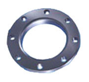
The lap joint flange derived it name lap joint as it is to be joint with a joint stub end. The flange has curved radius at its bore to accommodate a lap joint stub. A lap joint flange is similar in some ways as slip-on flange as a stub end is slipped on the flange having slightly larger radius then the stub end joint. lap joint stub and flange are joint together to make a assembly. Thus lap joint flange allows easy dismantling of system assembly. We manufacture lap joint flange in different sizes and standards.
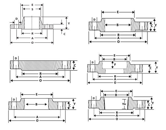
| DIMENSIONS OF CLASS 150 FLANGES (ANSI B 16.5) (in mm) | ||||||||||||||||
|---|---|---|---|---|---|---|---|---|---|---|---|---|---|---|---|---|
| Nominal Pipe Size |
Flange Dia 'O' |
Dia of Bolt Circle 'A' |
Dia of Bolt Holes 'D' |
No. of Holes |
Thk of Flange 'C' |
Diameter at Weld Bevel | Dia of Hub 'E' |
Length Through Hub | Bore 'B' | Dia of R/F R |
Depth of Socket F |
Length of Threading |
||||
| S/O & S/W Y |
W/N Y |
L/J Y |
S/O & S/W B |
L/J B |
||||||||||||
| 1/2'' | 15 | 88.9 | 60.3 | 15.9 | 4 | 11.1 | 21.3 | 30.2 | 15.9 | 47.6 | 15.9 | 22.3 | 22.9 | 34.9 | 9.5 | 15.9 |
| 3/4'' | 20 | 98.4 | 69.8 | 15.9 | 4 | 12.7 | 26.7 | 38.1 | 15.9 | 52.4 | 15.9 | 27.7 | 28.2 | 42.9 | 11.1 | 15.9 |
| 1'' | 25 | 107.9 | 79.4 | 15.9 | 4 | 14.3 | 33.5 | 49.2 | 17.5 | 55.6 | 17.5 | 34.5 | 35.0 | 50.8 | 12.7 | 17.5 |
| 1 ¼'' | 32 | 117.5 | 88.9 | 15.9 | 4 | 15.9 | 42.2 | 58.7 | 20.6 | 57.1 | 20.6 | 43.2 | 43.7 | 63.5 | 14.3 | 20.6 |
| 1 ½'' | 40 | 127.0 | 98.4 | 15.9 | 4 | 17.5 | 48.3 | 65.1 | 22.2 | 61.9 | 22.2 | 49.5 | 50.0 | 73.0 | 15.9 | 22.2 |
| 2'' | 50 | 152.4 | 120.6 | 19.0 | 4 | 19.0 | 60.4 | 77.8 | 25.4 | 63.5 | 25.4 | 62.0 | 62.5 | 92.1 | 17.5 | 25.4 |
| 2 ½'' | 65 | 177.8 | 139.7 | 19.0 | 4 | 22.2 | 73.1 | 90.5 | 28.6 | 69.8 | 28.6 | 74.7 | 75.4 | 104.8 | 19.0 | 28.6 |
| 3'' | 80 | 190.5 | 152.4 | 19.0 | 4 | 23.8 | 88.9 | 107.9 | 30.2 | 69.8 | 30.2 | 90.7 | 91.4 | 127.0 | 20.6 | 30.2 |
| 3 ½'' | 90 | 216.0 | 177.8 | 19.0 | 8 | 23.8 | 101.6 | 122.2 | 31.7 | 71.4 | 31.7 | 103.4 | 104.1 | 140.0 | 20.6 | 31.7 |
| 4'' | 100 | 228.6 | 190.5 | 19.0 | 8 | 23.8 | 114.3 | 134.9 | 33.3 | 76.2 | 33.3 | 116.1 | 116.8 | 157.2 | 23.8 | 33.3 |
| 5'' | 125 | 254.0 | 215.9 | 22.2 | 8 | 23.8 | 141.2 | 163.5 | 36.5 | 88.9 | 36.5 | 143.8 | 144.5 | 185.7 | 23.8 | 36.5 |
| 6'' | 150 | 279.4 | 241.3 | 22.2 | 8 | 25.4 | 168.4 | 192.1 | 39.7 | 88.9 | 39.7 | 170.7 | 171.4 | 215.9 | 27.0 | 39.7 |
| 8'' | 200 | 342.9 | 298.4 | 22.2 | 8 | 28.6 | 219.2 | 246.1 | 44.4 | 101.6 | 44.4 | 221.5 | 222.2 | 269.9 | 31.7 | 44.4 |
| 10'' | 250 | 406.4 | 361.9 | 25.4 | 12 | 30.2 | 273.0 | 304.8 | 49.2 | 101.6 | 49.2 | 276.3 | 277.4 | 323.8 | 33.3 | 49.2 |
| 12'' | 300 | 482.6 | 431.8 | 25.4 | 12 | 31.8 | 323.8 | 365.1 | 55.6 | 114.3 | 55.6 | 327.1 | 328.2 | 381.0 | 39.7 | 55.6 |
| 14'' | 350 | 533.4 | 476.2 | 28.6 | 12 | 34.9 | 355.6 | 400.0 | 57.1 | 127.0 | 79.4 | 359.1 | 360.2 | 412.7 | 41.3 | 57.1 |
| 16'' | 400 | 596.9 | 539.7 | 28.6 | 16 | 36.5 | 406.4 | 457.2 | 63.5 | 127.0 | 87.3 | 410.5 | 411.2 | 469.9 | 44.4 | 63.5 |
| 18'' | 450 | 635.0 | 577.8 | 31.7 | 16 | 39.7 | 457.2 | 504.8 | 68.3 | 139.7 | 96.8 | 461.8 | 462.3 | 533.4 | 49.2 | 68.3 |
| 20'' | 500 | 698.5 | 635.0 | 31.7 | 20 | 42.9 | 508.0 | 558.8 | 73.0 | 144.5 | 103.2 | 513.1 | 514.3 | 584.2 | 54.0 | 73.0 |
| 24'' | 600 | 812.8 | 749.3 | 34.9 | 20 | 47.6 | 609.6 | 663.6 | 82.5 | 152.4 | 111.1 | 615.9 | 615.9 | 692.1 | 63.5 | 82.5 |
Note : Thickness 'C' is inclusive of Raised Face Thickness of 1.65 MM. For Class 150
A class 150 flange can be created from various materials like stainless steel, carbon steel, ductile iron, cast iron, etc and is resistant to abrasion & corrosion with high durability. Flanges such as American standard flanges, British standard flanges and German standard flanges created using above mentioned materials have separate pressure ratings.
The pressure rating of flanges depends on various factors which we will look at in the following section.
Flanges are able to resist different pressure values at different & varied temperatures. With increase in temperature pressure rating of a flange decreases. Let us take an example to illustrate what happens; Class 150 flanges rates to about 270 PSIG (in ambient conditions), at 400 F a PSIG of 180, at 600 F a PSIG of 150 & 75 PSIG at 800 F. So it all depends on the fluid’s operating temperature.