Weld neck flanges are flanges in which welding is done on the neck of the flange thus giving its name weld neck flange. The design of weld neck flange is such that it reduces stress coming on the base of flange by transferring it on pipe thus transferring heavy concentration of pressure only on flange. The I.D of both pipe and flange matches there by reducing turbulence and erosion in the pipe due to continuous flow and stagnating particulates. Weld neck flanges are used in critical high pressure areas thus making it the most preferred butt weld flanges amongst all flanges. We are amongst the biggest exporters of weld neck flanges in India.
| DIMENSIONS OF CLASS 150 FLANGES (ANSI B 16.5) (in mm) | ||||||||||||||||
|---|---|---|---|---|---|---|---|---|---|---|---|---|---|---|---|---|
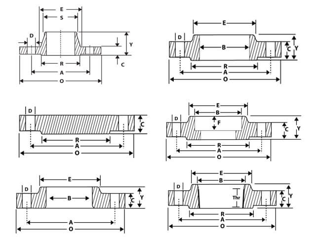
| Nominal Pipe Size |
Flange Dia 'O' |
Dia of Bolt Circle 'A' |
Dia of Bolt Holes 'D' |
No. of Holes |
Thk of Flange 'C' |
Diameter at Weld Bevel | Dia of Hub 'E' |
Length Through Hub | Bore 'B' | Dia of R/F R |
Depth of Socket F |
Length of Threading |
||||
| S/O & S/W Y |
W/N Y |
L/J Y |
S/O & S/W B |
L/J B |
||||||||||||
| 1/2'' | 15 | 88.9 | 60.3 | 15.9 | 4 | 11.1 | 21.3 | 30.2 | 15.9 | 47.6 | 15.9 | 22.3 | 22.9 | 34.9 | 9.5 | 15.9 |
| 3/4'' | 20 | 98.4 | 69.8 | 15.9 | 4 | 12.7 | 26.7 | 38.1 | 15.9 | 52.4 | 15.9 | 27.7 | 28.2 | 42.9 | 11.1 | 15.9 |
| 1'' | 25 | 107.9 | 79.4 | 15.9 | 4 | 14.3 | 33.5 | 49.2 | 17.5 | 55.6 | 17.5 | 34.5 | 35.0 | 50.8 | 12.7 | 17.5 |
| 1 ¼'' | 32 | 117.5 | 88.9 | 15.9 | 4 | 15.9 | 42.2 | 58.7 | 20.6 | 57.1 | 20.6 | 43.2 | 43.7 | 63.5 | 14.3 | 20.6 |
| 1 ½'' | 40 | 127.0 | 98.4 | 15.9 | 4 | 17.5 | 48.3 | 65.1 | 22.2 | 61.9 | 22.2 | 49.5 | 50.0 | 73.0 | 15.9 | 22.2 |
| 2'' | 50 | 152.4 | 120.6 | 19.0 | 4 | 19.0 | 60.4 | 77.8 | 25.4 | 63.5 | 25.4 | 62.0 | 62.5 | 92.1 | 17.5 | 25.4 |
| 2 ½'' | 65 | 177.8 | 139.7 | 19.0 | 4 | 22.2 | 73.1 | 90.5 | 28.6 | 69.8 | 28.6 | 74.7 | 75.4 | 104.8 | 19.0 | 28.6 |
| 3'' | 80 | 190.5 | 152.4 | 19.0 | 4 | 23.8 | 88.9 | 107.9 | 30.2 | 69.8 | 30.2 | 90.7 | 91.4 | 127.0 | 20.6 | 30.2 |
| 3 ½'' | 90 | 216.0 | 177.8 | 19.0 | 8 | 23.8 | 101.6 | 122.2 | 31.7 | 71.4 | 31.7 | 103.4 | 104.1 | 140.0 | 20.6 | 31.7 |
| 4'' | 100 | 228.6 | 190.5 | 19.0 | 8 | 23.8 | 114.3 | 134.9 | 33.3 | 76.2 | 33.3 | 116.1 | 116.8 | 157.2 | 23.8 | 33.3 |
| 5'' | 125 | 254.0 | 215.9 | 22.2 | 8 | 23.8 | 141.2 | 163.5 | 36.5 | 88.9 | 36.5 | 143.8 | 144.5 | 185.7 | 23.8 | 36.5 |
| 6'' | 150 | 279.4 | 241.3 | 22.2 | 8 | 25.4 | 168.4 | 192.1 | 39.7 | 88.9 | 39.7 | 170.7 | 171.4 | 215.9 | 27.0 | 39.7 |
| 8'' | 200 | 342.9 | 298.4 | 22.2 | 8 | 28.6 | 219.2 | 246.1 | 44.4 | 101.6 | 44.4 | 221.5 | 222.2 | 269.9 | 31.7 | 44.4 |
| 10'' | 250 | 406.4 | 361.9 | 25.4 | 12 | 30.2 | 273.0 | 304.8 | 49.2 | 101.6 | 49.2 | 276.3 | 277.4 | 323.8 | 33.3 | 49.2 |
| 12'' | 300 | 482.6 | 431.8 | 25.4 | 12 | 31.8 | 323.8 | 365.1 | 55.6 | 114.3 | 55.6 | 327.1 | 328.2 | 381.0 | 39.7 | 55.6 |
| 14'' | 350 | 533.4 | 476.2 | 28.6 | 12 | 34.9 | 355.6 | 400.0 | 57.1 | 127.0 | 79.4 | 359.1 | 360.2 | 412.7 | 41.3 | 57.1 |
| 16'' | 400 | 596.9 | 539.7 | 28.6 | 16 | 36.5 | 406.4 | 457.2 | 63.5 | 127.0 | 87.3 | 410.5 | 411.2 | 469.9 | 44.4 | 63.5 |
| 18'' | 450 | 635.0 | 577.8 | 31.7 | 16 | 39.7 | 457.2 | 504.8 | 68.3 | 139.7 | 96.8 | 461.8 | 462.3 | 533.4 | 49.2 | 68.3 |
| 20'' | 500 | 698.5 | 635.0 | 31.7 | 20 | 42.9 | 508.0 | 558.8 | 73.0 | 144.5 | 103.2 | 513.1 | 514.3 | 584.2 | 54.0 | 73.0 |
| 24'' | 600 | 812.8 | 749.3 | 34.9 | 20 | 47.6 | 609.6 | 663.6 | 82.5 | 152.4 | 111.1 | 615.9 | 615.9 | 692.1 | 63.5 | 82.5 |
Note : Thickness 'C' is inclusive of Raised Face Thickness of 1.65 MM. For Class 150
A class 150 flange can be created from various materials like stainless steel, carbon steel, ductile iron, cast iron, etc and is resistant to abrasion & corrosion with high durability. Flanges such as American standard flanges, British standard flanges and German standard flanges created using above mentioned materials have separate pressure ratings.
The pressure rating of flanges depends on various factors which we will look at in the following section.
Flanges are able to resist different pressure values at different & varied temperatures. With increase in temperature pressure rating of a flange decreases. Let us take an example to illustrate what happens; Class 150 flanges rates to about 270 PSIG (in ambient conditions), at 400 F a PSIG of 180, at 600 F a PSIG of 150 & 75 PSIG at 800 F. So it all depends on the fluid’s operating temperature.